

 It is only your donations that keep this website going. If we've helped you, please pay the favour forward and help others by keeping this content alive. You can do this by clicking here and donating. Thank you, for whatever you decide to give.
- This guide describes how to overhaul and restore your Mercedes instrument cluster (dash board or console) to correct any fading LCD multifunctional displays that have missing pixels. The common LCD displays that require pixel repair are the clock and temperature screens. Although this guide is for a 1996-2001 Mercedes E-Class it should apply in general to pretty much any variant or model (C-Class, later E-Class etc.)
- I've recently bought a Mercedes Benz E-Class (W210) that was in fabulous condition bar one or two minor things. As I like to restore my cars I've set about putting all those niggles right. One of the main things was a blown instrument panel bulb and some fading pixels on the LCD's. There is a huge amount of information out there on how to do this, and without it (and some excellent guides) I would never have been able to do the fix so easily. However, all of the information is not in one place and many of the guides miss out key bits of information and some use very risky procedures. So I decided to write this one to fill in those gaps and solve those issues!
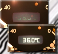
- There are three methods for repairing fading pixels on your LCD screens. Fading pixels are a common failure on the clock and temperature displays for the E-Class and can be traced to the ribbon cable's junction with the PCB. The ribbon cable is simply glued and pressed against the PCB on the E-Class and over time the rubbers that press it down become less elastic and the glue fails leading the ribbon to become detached. You can either use the simple fix of increasing the rubber pressure on the ribbon (works sometimes, less successfully on the clock), replace the ribbon cable with a new one (more complex but inexpensive) or replace the LCD and ribbon assembly (simpler but expensive). However, the first thing to do is to work out whether it really is a ribbon cable fault as blank LCD's. can be simply down to a failure in the backlighting (click here for a guide on how to replace the backlighting for your LCD displays). Have a look at the photo to the left, if your LCD looks like the first image in the photo this then it is probably a ribbon cable fault.
- Assuming you have a ribbon cable fault, I'd always recommend trying the simple fix of increasing the rubber pressure on the ribbon as a first point of call - you will find the procedure for this in the sections below. If this doesn't work you have the option of either replacing the ribbon or the whole LCD assembly (ribbon and LCD). Of the two procedures I'd recommend going for the former (replacing only the ribbon) only if you have some prior experience with electrics and/or are experienced at DIY. The real issue with replacing only the ribbon is aligning the contacts on the LCD side of the cable, this is really only a problem with the more complex and tiny clock LCD connectors. However, you should not be put off by this if you are confident working with your hands as it is not that difficult. If you buy the whole LCD assembly then this joint is already in place and you only need to worry about the PCB junction.
- LCD pixel repair is pretty easy and takes 30 mins to 1 hour. LCD ribbon cable or LCD assembly replacement is more tricky, but not difficult if you are used to working with general electrical items and have a steady hand. I took 1 hour 30 mins to fit my ribbons and complete the procedure.
- Both procedures carry some moderate risk. LCD pixel repair is the safest procedure of the two. The most you are likely to do is end up without a working LCD display. However there is a small risk in both procedures that you might have the exciting opportunity to drive a Mercedes without a working console, but only if you make a big mistake or get massively unlucky. This is very, very unlikely to happen (I've already had the dash board out 5 times and carried out both procedures), but you should understand that is is a very remote possibility whenever you work on an instrument panel or console no matter what you're doing.
- Minimise that Small Risk - Get prepared and take precautions
- 1. The first precaution is to prepare a clean, non metallic (wood) work surface for working on the dash and get all your tools prepared in advance. Never work on a wet day when there might be rain unless you're undercover. Also never work during a thunder storm on electrics even inside, this was never an issue in the old days when microchips were not common in cars, but with modern technology comes the risk of frying a microchip with ambient voltage build-up.
- 2. The second precaution (and most important) is to always disconnect the car battery (despite some advice on the internet elsewhere). Never skip this step. Voltage can be supplied to the console at all times when the battery is connected, pulling and connecting live wires is not a good thing for PCBs. Yes, you'll probably get away with it if you don't, but why risk it? The reason why some people advise on leaving the battery connected is to avoid the glitches that need to be reset in windows and sunroof after the car's ECU boots back up - but the reset procedures are easy and the risk of rare permanent glitches that can only be reset by a dealer are far smaller than the risk of damage through connecting a live wire.
- 3. The third precaution is to minimise static build up, especially if you're repairing the LCD's. Static will destroy microchips on PCBs. Just replacing a bulb carries virtually no risk of damage to the PCB through static, but if you're accessing it directly to repair the LCD's then you need to take precautions. First wear only cotton clothing and ditch those synthetic mechanics gloves. Avoid directly touching any PCB, hold it by it's edges where there aren't contacts. Either buy a cheap earth strap for you wrist (only £3 but not really necessary for this) or earth yourself regularly and before you touch the PCB (touching a metal household tap is great for this).
- This quick fix works very well for fading pixels on your temperature gauge, but less well for the more complex clock ribbon. The results will all depend on the amount of corrosion on your ribbon cable contacts. The idea is a simple one - push the ribbon cables down harder onto the PCB by inserting a small strip of packing material beneath the existing rubber pressure pads. This simple procedure is shown below:
 1. Before you start make sure you have read the "Get prepared" section of this guide. Make sure you have at least a 1" long pencil rubber (eraser), a sharp hobby knife, a ruler and some tweezers to hand. If you have any blown bulbs in your instrument cluster then you should replace them as part of this procedure. You can find a guide here for replacing instrument panel bulbs on the E-Class and other models. Also it is a good idea to have a few spare green instrument panel bulbs (see above guide) as you may cause a bulb to cold blow as part of this procedure.
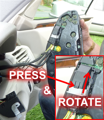
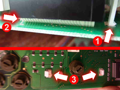
 - 2. First you need to remove the instrument cluster from your dashboard, click here for the procedure. This is easy to do and this guide includes details of the simple tools you need to make or buy. The photo above shows the final steps of removing the cables after the cluster has been pulled from the dashboard - this should give you an idea of what's required and what is detailed in this guide.
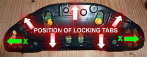 3. If you followed the above guide, you should now have your Mercedes instrument cluster sitting on your workbench and ready for disassembly. If you are thinking of replacing any bulbs at the same time, do not do it yet - wait until you have fixed the ribbons and reassembled the instrument cluster. The instrument cluster has 2 main parts to the black case that are held together by 6 locking tabs. The locations of these locking tabs is shown in the photo to the right. However, it is important to note that the 2 locking tabs marked with a green 'X' should not be prised up at this point as they hold the white casing for the warning light channels and are not required to separate the halves. The rest of the locking tabs need to be carefully levered up with a screwdriver to separate the front and back parts of the instrument cluster. Once you have prised apart the black casing you will be left with an empty front half (dial glass and case) and a back half that contains the PCB with all the dials and electronics (do not place this face down or you may break the dials!).
 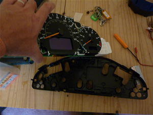 4. Now you need to separate the PCB with the dials on it from the black back of the instrument cluster case. This is held in place by all 6 of the locking tabs, 4 are just friction fits but the 2 tabs marked with the green 'X' in the above photo need to be prised open from their locking positions in the white plastic light channels. Gently prise out the PCB from the case back and then lay it on the work bench so that the dials are upwards (always put it this way up if you have finished handling the PCB)
 - 5. It is time to fix those ribbon cables. The dials and LCD displays are set in a white assembly that is held onto the PCB board by clips that are latched into the PCB through small holes (see numbers [1] and [3] in the photo to the right). You are not going to fully separate the white assembly, just lever it up enough to push a thin sliver of pencil rubber (eraser) behind the ribbon cable (see number [2] in the photo) that will increase the pressure on it when you snap the white assembly back into place. This should force the contacts in the ribbon cable onto the contacts etched onto the PCB. This is the cause of your missing pixels on your LCD displays as the original pink rubber held in the black shield (see photo) will have become inelastic over time. The sliver of pencil rubber (eraser) you need to cut should be longer than the width of the ribbon cable and of about 1mm thickness (you can increase the thickness if you find that it has not fixed the missing pixels after reassembly). Use some tweezers to carefully slide it into place (see [2] in photo) and then click the white assembly back into place, latching its tabs into the PCB again. It is a good idea to secure the white locking tabs at this point as the extra pressure you have introduced can force them partially back out which will cause another missing pixel issue. You can do this very simply by inserting a non-conductive material behind them to hold them in place (see [3] in photo)- I used some strip wood as the packing which I then snapped off flush with the PCB, but a cocktail stick would work just as well. The beauty of this approach is that you can easily remove the packing very easily if you need to repeat this whole procedure.
 6. You can now reassemble the instrument cluster. This is pretty much a reverse of the disassembly procedure above with a couple of changes. First align the PCB and white light channels with the black case back of the cluster and then wiggle/click it into place. Now it's time to refit the black front of the instrument cluster with the dial windows. This is where things can go wrong. The front of the instrument case holds 2 warning light icon sheets (i.e. ignition light icon etc.) and these are only held in place by a 3 raised points on the case mating with 3 holes in the icon sheets (see the photo to the left). The pressure that keeps them mated is provided from the cluster case back, which of course you have removed. What this means is the icon sheets tend to fall out or become misaligned during reassembly unless you are very careful. This can be very frustrating, but luckily there is a simple solution: Prop the front of the case up using books (see photo above) until it is level, then fit the icon sheets (these will be held in place against the raised points by gravity) and finally carefully lower the PCB/instrument case back assembly into position and snap it into place. Once the case back is on, check that the icon sheets are still aligned by wiggling them (there are slots on the side to do this) - they should move a little and you should feel them held back from moving more by the raised points.
 - 7. Now that you have completely reassembled the instrument cluster you should replace/upgrade any bulbs that you need to (click here for the Mercedes instrument bulb replacement procedure) and then re-fit it back into your E-class (click here for the Mercedes instrument cluster refitting procedure). Once it's refitted test it and do not be too worried if the missing pixels fix doesn't work the first time around as you may need to repeat the above procedure to get the thickness of the rubber just right. However, if you continue to fail you can replace the entire LCD assemblies or their ribbon cables to fix your pixel issues (see procedure in the section below). For my E-Class the "Quick Fix" worked on the temperature LCD perfectly, but only partly worked on the clock so in the end I replaced the ribbon cables.
- Depending on the manufacturer of the parts you buy the replacement procedure will be different, but instructions should come with the parts. However the general procedure for disassembling the instrument cluster is listed in the "quick fix" (repair Option 1) section in this guide. This is well worth a read as it will give you a guide as to what to expect in terms of removal and disassembly of the instrument cluster.
- So if you have to replace the ribbon cable what parts do you need and where do you get them? Well, ribbon cables and LCD assemblies for the E-Class are readily available all over the internet, just use Google. You'll find loads on Ebay (don't touch them though!). Anyway, that's the good news, now the warnings when you're buying your parts as there's a lot of junk around:
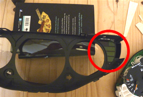
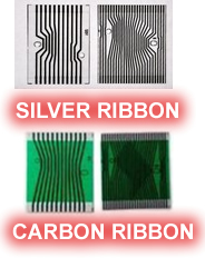 First and most importantly, always buy from a reputable merchant and never buy used (they will not work). Ask if your parts are provided with instructions, if not then walk away and do not buy them. This is especially important if you are just buying the ribbon cables as there are a lot of junk ribbon cables on the market that simply will not work. If your ribbon cables are costing less than £10 then they are probably junk, so do not buy them. Always pay more and buy silver ribbon cables rather than the carbon ribbon cables. Carbon cables are often junk cables (they're easier to produce) and they are more tricky to fit as most need to be heated with a soldering iron. If you do somehow manage to get some quality carbon cables then they'll probably work OK, but they're not going to last more than 5 years. Given all that, I'd pay some more money and get some OEM silver cables. You can see the difference between Mercedes E-Class carbon and silver ribbon cables in the photo to the right so you know what you're looking for.
Quickly & cheaply fix the missing picxels in a fading LCD multifunction display in your instrument panel.
PLEASE SUPPORT US |
| If we helped save you money, please pay the favour forward and help support the upkeep of this site and its guides for others. Just click a button below. |
 |
 |
 |
| Big thanks from us for your help! |
Please share your knowledge. |
| Many people have already helped others through this site by contributing information and techniques. If you have something you want to contribute, please click here to contact us. You'll be credited on this site and you'll have shared what you know to help the community. |
| Thanks to all who have contributed |